This project stretches the idea of light painting into something closer to a printer: a rig that knows where it is in space, paints color into the long exposure one sample at a time, and is steered by software so the result can be deliberate—not just beautiful scribbles.
Hardware Setup
The hardware story is intentionally simple on paper: a Raspberry Pi Zero W2 watches the scene, a Seeed XIAO drives the LED and IR illuminator, and an ELRS link moves commands between them fast enough to matter.
In practice, each piece has a job. ELRS is the low-latency bridge. The IR camera estimates where the rig is in the frame. The IR emitter keeps the scene legible for that tracker. The NeoPixel is the brush—one controllable point of color in space and time.
Components
- Raspberry Pi Zero W2
- Seeduino XIAO
- IR Camera
- IR Emitter
- NeoPixel LED
- ELRS Receiver
- ELRS Transmitter
Wiring
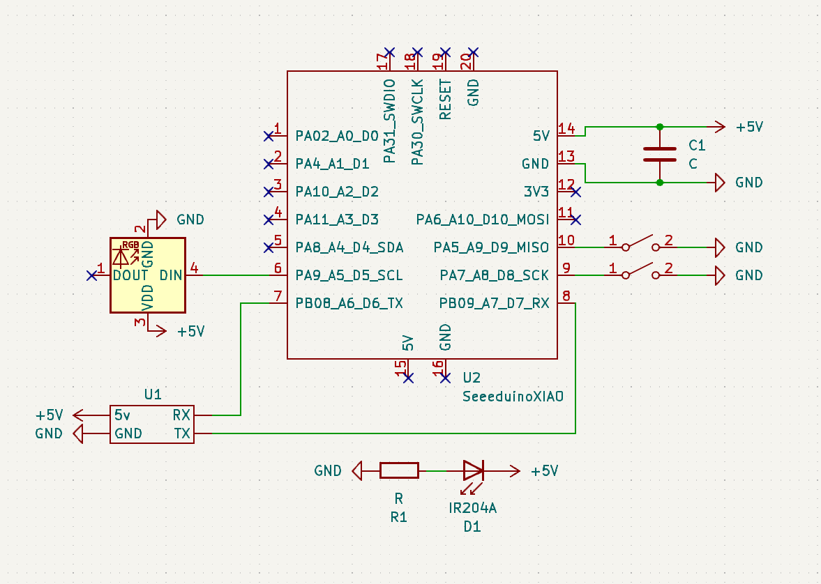
Seeduino XIAO
The schematic for the hardware setup is as follows:
Raspberry Pi Zero W2
The schematic for the hardware setup is as follows:
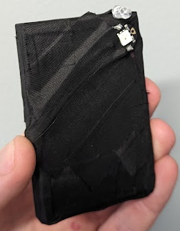
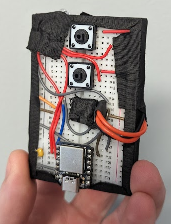
Photos
Software Setup
Software is where the “printer” metaphor shows up: the Pi turns pixels into poses, the radio carries those poses to the microcontroller, and the microcontroller turns poses into LED updates—many times per second.
Control Flow Diagram
Sequence Diagram
ELRS Airport
The ELRS airport is used to communicate between the Raspberry Pi Zero W2 and the Seeduino XIAO. The ELRS airport is a simple serial connection that is used to send and receive data between the two devices.
ELRS airport is using 2.4 GHz frequency to communicate between the devices. And can also be used for long-range communication.
ELRS airport also has a much higher data rate than other communication protocols with a baud rate of 460800, it can send and receive data at a much faster rate. This is important for the light painting device as it needs to send and receive data quickly.
Raspberry Pi Zero W2
The Raspberry Pi Zero W2 is responsible for capturing the image and processing it. The image is processed to determine the position of the device. The position is then sent to the Seeduino XIAO using the ELRS transmitter.
The script running on the PI is a heavily modified version of the Ball Tracking with OpenCV tutorial by Adrian Rosebrock. The script captures the image and processes it to determine the position of the device.
Main Imports
import cv2
import imutils
import serail
from picamera2 import Picamera2
cv2 is the main workhorse for image processing. imutils is used to resize the image. picamera2 is used to capture the image using the NoIR camera. Then, the position data is sent to the Seeduino XIAO using the serial library over ELRS airport.
Seeduino XIAO
The Seeduino XIAO is responsible for controlling the NeoPixel LED. The Seeduino XIAO receives the position data from the Raspberry Pi Zero W2 using the ELRS receiver. The Seeduino XIAO then controls the NeoPixel LED based on the position data.
How to load the image
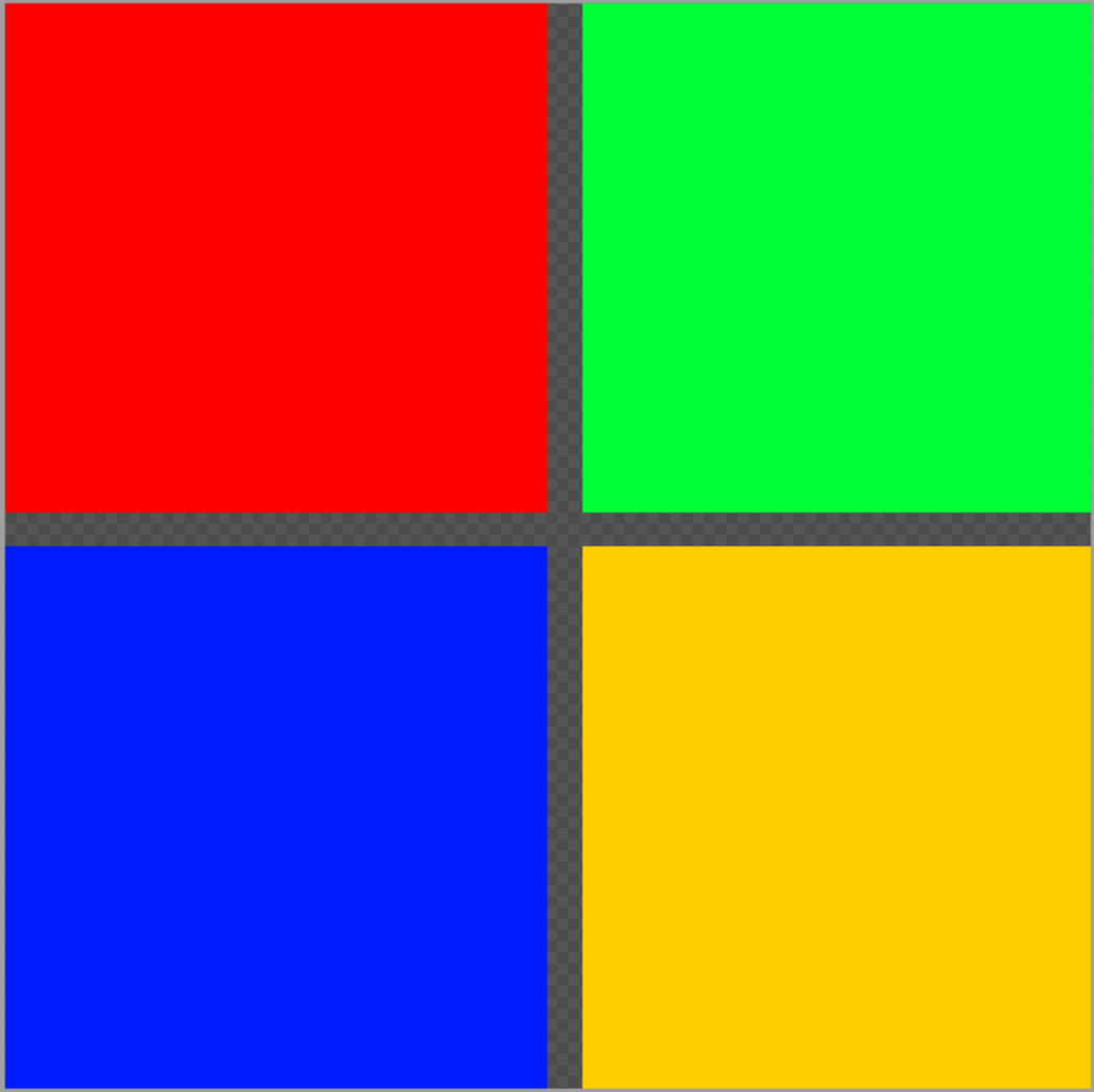
To get the image into the Seeduino XIAO, we need to convert the image into a format that can be read by the Seeduino XIAO. The image is converted into a 2D array of RGBA values. We do this using Piskel, a free online tool for creating pixel art.
The output is as follows:
Piskel exported data
#include <stdint.h>

#define NEW_PISKEL_FRAME_COUNT 1
#define NEW_PISKEL_FRAME_WIDTH 32
#define NEW_PISKEL_FRAME_HEIGHT 32

/* Piskel data for "New Piskel" */

uint32_t new_piskel_data[1][1024] = {{0xff0000ff, 0xff0000ff, 0xff0000ff, 0xff0000ff, 0xff0000ff, 0xff0000ff, 0xff0000ff, 0xff0000ff, 0xff0000ff, ..., 0xff0000ff, 0xff0000ff, 0xff0000ff, 0xff0000ff, 0xff0000ff, 0xff0000ff, 0xff0000ff, 0xff0000ff, 0xff0000ff, 0xff0000ff, 0xff0000ff, 0xff0000ff, 0xff0000ff, 0xff0000ff, 0xff0000ff, 0xff0000ff, 0xff0000ff, 0xff0000ff, 0xff0000ff, 0xff0000ff, 0xff0000ff, 0xff0000ff, 0xff0000ff, 0xff0000ff, 0xff0000ff, 0xff0000ff, 0xff0000ff, 0xff0000ff}};
How to use the image
We can use this exported file (first convert it from .c to .h) and include it in our Seeduino XIAO code.
#include "New Piskel.h"
#include "image.h"
...
image img1(new_piskel_data[0], NEW_PISKEL_FRAME_WIDTH, NEW_PISKEL_FRAME_HEIGHT);
We can then access all of the individual pixels using the img1 object.
int x, y;
int r, g, b, a;

img1.getPixelValue(x, y, &r, &g, &b, &a);
This will give us the RGBA value of the pixel at position x, y using the following function:
void image::getPixelValue(int x, int y, int *r, int *g, int *b, int *a)
{
    // Read the pixel at (x, y) and swap byte order from BGRA to RGBA
    uint32_t pixel = __builtin_bswap32(_imageArray[x * _width + y]);

    *r = (pixel >> 24) & 0xFF; // Extract the red component
    *g = (pixel >> 16) & 0xFF; // Extract the green component
    *b = (pixel >> 8) & 0xFF;  // Extract the blue component
    *a = pixel & 0xFF;         // Extract the alpha component
}
After we have the pixel data, we can then control the NeoPixel LED based on the pixel data.
Demo
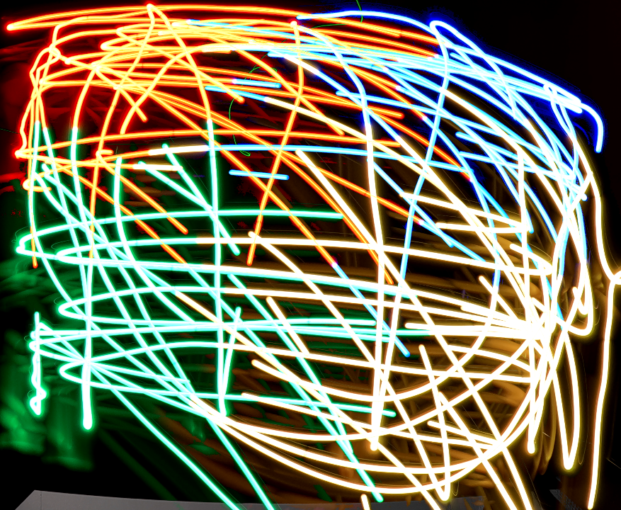
These runs are early—thin strokes mean you need a lot of passes, and color switching still isn’t as snappy as it could be—but they’re enough to prove the loop: design → motion → light → photograph.
Below are a few before/after/overlaid comparisons. Open each panel if you want the raw stills.
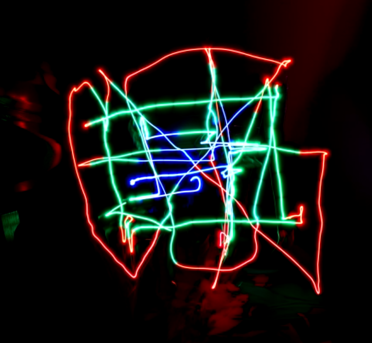
Square in a Square in a Square (Input)
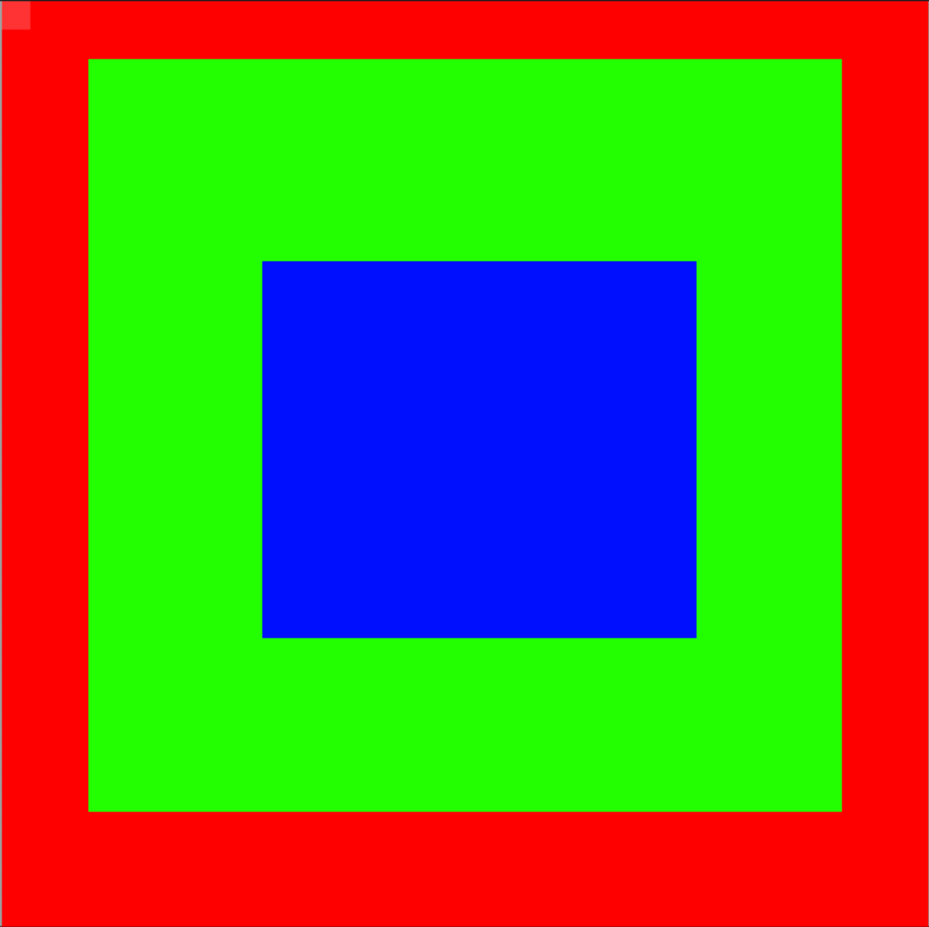
Square in a Square in a Square (Output)
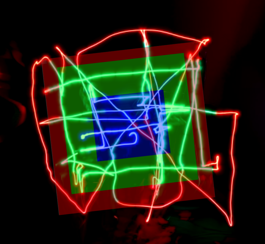
Square in a Square in a Square (Overlaid)
Microsoft (Input)
Microsoft (Output)
Microsoft (Overlaid)
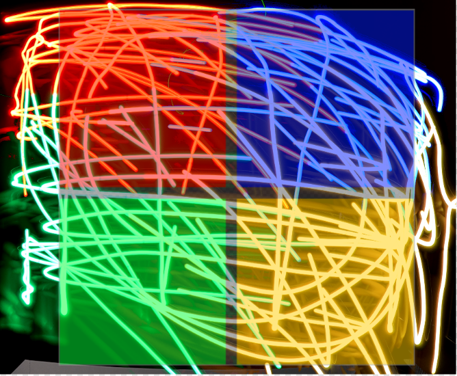
That limitation is visible in the photos: it’s not a perfect “screen in the air” yet. But it is a real, end-to-end pipeline—tracking, transport, and pixel control all working together.
Conclusion
This iteration already hits the original bar: motion in X/Y, programmable color, and enough bandwidth to chase a moving brush. The fun problems left are the classic ones: faster updates, denser sampling, and a tracking stack that doesn’t fight you when the scene gets messy.
If I pick this up again, I’d start with two upgrades: a faster path from frame → pose, and a more forgiving localization approach than IR-only tracking. GPS is probably the wrong tool indoors—but a better sensor fusion story (or simply better optics) would go a long way.